Showing posts with label Arduino. Show all posts

Tuesday, 22 October 2013

Raspberry Pi and Arduino

I am putting together a data logger for the biogas generator.

I would like it networked so I don't have to go out in the cold, so will use a raspberry pi.   To make interfacing the sensors easy I will connect the Pi to an Arduino microcontroller.   This is a bit over the top as I should be able to do everything I need using the Pi's GPIO pins, but Arduino has a lot of libraries to save me programming....

To get it working I installed the following packages using:
apt-get install gcc-avr avr-libc avrdude arduino-core arduino-mk

To test it, copy the Blink.ino sketch from /usr/share/arduino/examples/01.Basics/Blink/ to a user directory.
Then create a Makefile in the same directory that has the following contents:
ARDUINO_DIR  = /usr/share/arduino
TARGET       = Blink
ARDUINO_LIBS =
BOARD_TAG    = uno
ARDUINO_PORT = /dev/ttyACM0
include /usr/share/arduino/Arduino.mk
Then just do 'make' to compile it, then upload to the arduino (in this case a Uno) using:
avrdude -F -V -p ATMEGA328P -c arduino -P/dev/ttyACM0  -U build-cli/Blink.hex
The LED on the Arduino Uno starts to blink - success!

Saturday, 19 October 2013

Small Scale Biogas Generator

I heard on the radio last week that some farmers are using anaerobic digesters to produce methane-rich biogas from vegetable waste.
This got me wondering if we could use our domestic waste to produce usable fuel gas - maybe to heat the greenhouse or something similar.

I thought I would make a small scale experimental digester to see if it works, and what amount of gas it makes, to see if it is worth thinking about something bigger.

My understanding is that the methane producing bacteria work best at over 40 degC, so I will heat the digester.  I will do this electrically for the experimental set up because it is easy, and I can measure the energy consumption easily that way.

I am using a 25 litre fermentation vessel for the digester - I got one with a screw on cap rather than a bucket so I can run it at slightly elevated pressure if it starts to make gas.
For simplicity I got a 1 m2 electric underfloor heating blanket to heat the vessel.  I will use an electro-mechanical thermostat as a protection device in case the electronic temperature controller I will produce looses its marbles and tries to melt the vessel.


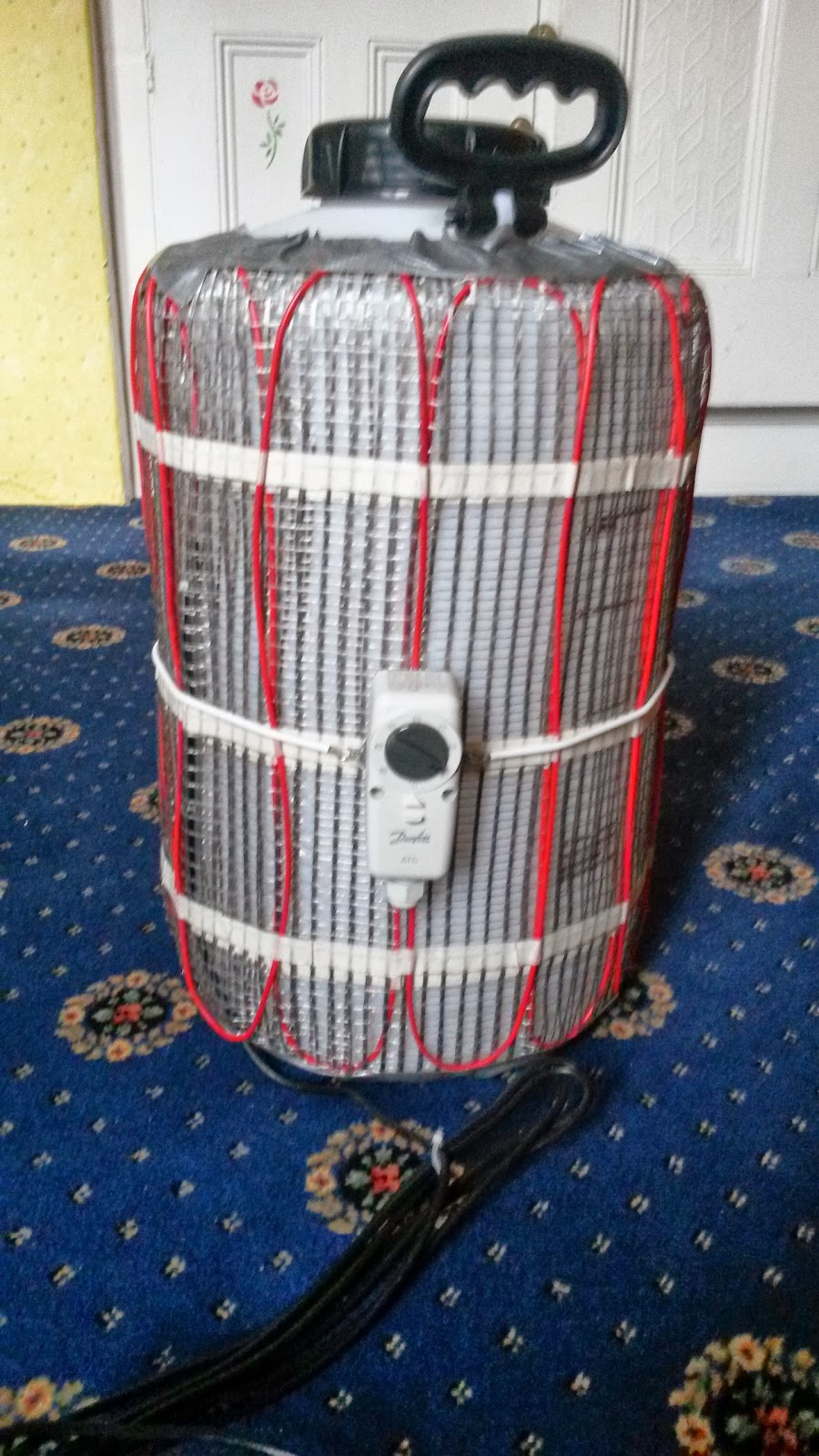
To start with I just wrapped the blanket around the vessel.

But before I tested it I realised that this approach is no good - the vessel will not be full of liquid, so I do not want the heating element all the way up the sides.


So, I removed the heating element from the underfloor heating mat, and wrapped it around the bottom of the vessel instead.


To improve heat transfer between the heating element and the vessel, I pushed as much silicone grease as I could get in around the element wires, then wrapped it in gaffer tape to make sure it all held together and I don't get covered in grease:

It is looking promising now - the element gets warm, and the thermostat trips it out when it starts to get hot.  The dead band on the thermostat is too big to be useful for this application (it is about 10 degC), so I will just use that as an over-heat protection device, and us an Arduino microcontroller to control and log the temperature.

To get the proof of concept prototype working, I think I need to:
  • Sort out a temperature controller - will use an arduino and a solid state relay to switch the heater elements on and off.
  • Gas Handling - I will need to do something with the gas that is generated, while avoiding blowing up the house or garage - I have seen somewhere where they recommend using an aluminised mylar baloon, which sounds like a good idea if I can find one.
  • Gas Composition Measurement - I will need to find out the proportion of methane to carbon dioxide that I am generating - still not sure how to do that.   It would be possible with a tunable IR laser diode, but not sure if that is feasible without spending real money.  Any suggestions appreciated!
  • Gas volume measurement - the other thing I am interested in is how much gas is generated - not sure how best to measure very low gas flow rates.  I am wondering about modifying a U-bend type airlock to detect how many bubbles pass through - maybe detect the water level changing before the bubble passes through.
If this looks feasible, the next stages of development would be:
  • Automate gas handling to use the gas generated to heat the digester - success would be making it self sustaining so that it generated enough gas to keep it warm.  That would mean scaling it up would produce excess gas that I could use for something, else.
  • Think about how far I can scale it up - depends on what fuel to use - kitchen and 'soft' garden waste is limited, so might have to look for something else....
Will post an update when I get it doing something.


Wednesday, 13 February 2013

Epileptic Seizure Detector (2)

Update to add another spectrum...

I have been working on setting up the Epileptic Seizure Detector.  I tried wearing it for a while, and simulating the shaking associated with a tonic-clonic seizure.   Some example spectra collected on the memory card are shown below:
This shows that the background noise level is at about 4 counts.   
Wearing the accelerometer on the biscep gives a peak up to about 8 counts at 7 Hz, but it is not well defined.  
Wearing the accelerometer on the wrist gives a much more well defined peak at 6-7 Hz. (and it raised an alarm nicely).

I have also tried an ADXL345 digital accelerometer.  The performance is similar to the analogue one, but I think it may be slightly more sensitive.  Example spectra with the accelerometer attached to the biscep are shown below.  ONe is a simulated fit.  The other is a false alarm going down the stairs.  Not that much difference!


Therefore I think there is scope for this set up to work if it is worn as a wrist watch, but just attaching it to other parts of the body may not be sensitive enough.

I wonder if I could make a wrist sensor that is watch sized, with a wireless link to a processor / alarm unit?

Not sure if I will be able to persuade Benjamin to wear a wrist sensor though....Might have to think about microphones.

Saturday, 9 February 2013

Epileptic Seizure Detector (1)

Our son worried us a bit a couple of weeks ago when he had quite a nasty fit, so I have been thinking about making an alarm to warn a carer that a person in their charge is having a seizure.

There are a few different ways to do this that I have thought of:

  1. Detect Movement using an accelerometer
  2. Detect the sounds associated with the movement using a microphone
  3. Monitor the movement with a CCTV camera and use image processing to detect the abnormal movement.
I am trying option 1 (accelerometer) first, but am working on the CCTV approach in parallel by learning OpenCV.

Because our son is autistic, it will be very difficult to get him to wear a device, so I hope to detect movement through the floorboard where he sleeps, but this will be much less sensitive than detecting it directly.  Therefore, this first proof of concept version is working by attaching the accelerometer to a limb to see if I can get it working.  The issues with it are:
  1. We do not want false alarms caused by normal movement - I am addressing this by using a fourier transform to filter out only a range of frequencies of movement, in the hope that I can select the characteristic shaking of a seizure, but not detect too much normal movement.
  2. A quick shake should not raise an alarm, so to set off an alarm the acceleration in the appropriate frequency band should be more than a threshold value for a specified length of time (3 sec currently).  This will give a warning 'pip'.   If the shaking continues for 10 sec, it raises a buzzing alarm.
  3. Sensitivity will be a problem for detecting it through the floor - will need to work on that another evening.
The system uses an Arduino microcontroller, connected to a Freescale MMA7361 three axis accelerometer.   The accelerometer is a tiny (5mm x 3mm) surface mount device, so soldering it is a challenge - you can see how I did it here.
To enable data logging so I can tune it to get the frequency response, threshold etc. the arduino is also connected to a real time clock module and a SD card module.
The completed prototype is shown below:
The code is in my Arduino Projects github repository.

And here is a simple demonstration of it working - you can hear the warning 'pip' and the alarm 'buzz' in the background when I shake my arm to simulate a seizure. 
Still quite a bit of work to do - build it on stripboard to make it more robust, then try attaching it to the floor and seeing if I can detect any signal from someone shaking.  If not, I will have to minaturise it to make it wearable, and train Benjamin to wear it....


Sunday, 16 December 2012

Approaching a working version of Arduino Solar Monitor

Christmas is coming, so I have to get a working version of the Arduino Solar Panel monitor.

My original intent was that it would have the following features:

  1. Measure the collector differential temperature.
  2. Infer the water flow rate from pump speed.
  3. Calculate the instantaneous power being collected.
  4. Calculate hourly and daily average powers.
  5. Log this information to an SD card.
  6. To achieve (5) easily, derive the time from an external Real-Time-Clock (RTC).
Now, features 1-3 are working, phew.   Feature 5 is implemented, but I need to think about what I really want (is daily average power useful?  Or should I just integrate total heat collected in a day?

Features 5 and 6 are proving troublesome, as I think I am starting to get to the limit of a single Arduino board (or more precisely the ATMega 328 controller on the board).

The main problem is that I am running out of RAM, and am going to have to give some serious thought to how to manage it better (just like old times programming a Zilog Z80A.....).

One problem is the number of different interfaces (and hence libraries) that I am having to use to achieve this.  The base software uses:
  1. OneWire.h and DallasTemperature.h to do the temperature monitoring, using a One-Wire bus.
  2. LiquidCrystal.h to drive the LCD display, using parallel data transfer
To add SD card support and a real time clock, I will need:
  1. Wire.h and DS1307RTC.h to access the real time clock from an I2C interface.
  2. SD.h to access the SD card from a SPI interface.
Each library uses a bit of ram , and there is only 2k of ram on the chip, so I am running out of it rapidly.  When I tried to add the RTC code, the board re-booted every few seconds, which I think was an out of memory issue.

So, the de-scoped system is not going to do SD card logging.  As compensation I have added switches to the two spare digital lines to use to provide a simple user interface so you can scroll between instantaneous, hourly and daily data, and maybe even set the clock (but I do worry about running out of RAM again if I get too adventurous!

Given this, I have put the 'Version 1' hardware together, and mounted it in a cheap 2 gang socket pattress box with a blank cover cut out to hold the board:
The toggle switch on the front is for the display back-light - I thought that would be easier than a push-button if you were trying to use buttons for the interface - the new buttons are facing the bottom of the picture on the side of the front panel, so you can't see them on this photo (and I made a mess of cutting the holes for them, so it looks a bit ugly...).

Right, just got to sort out the software now.  Current version is on github.

Sunday, 9 December 2012

Odd Behaviour of Arduino

I think I have got too used to working on large computers, which have essentially infinite resources, as far as my little projects are concerned, so I am having a bit of trouble with Arduino.   The two interesting problems I have seen are:


  1. Low Battery:  The symptoms were the device operating ok for quite a while (initially around an hour, but later ~5 minutes), then doing very unexpected things - what I saw was the pin 13 LED flashing on and off, but my software was not doing anything with that pin.   It looked like the board had just lost its marbles.   It turned out that the issue was low voltage on the 9V battery that was powering it - I did not realise initially because the LED back light on the display worked fine, which is the test I was using for 'it has got power'.  When I put a volt meter on it, it was only providing around 5.3V, so I think that this was insufficient to start the arduino properly...but surprisingly was enough to light the LED ok - I have always thought that LEDs need more power than little electronic devices, so if the LED is ok, it has enough power - this is not true, so I must think of another simple check!
  2. Out of Memory:  My solar thermal monitor now works nicely with an LCD display, and I made a simple test program to write data to an SD card.  The odd thing is that merging the two together results in a program that compiles ok and loads onto the device, but when it tries to write to the SD card, the arduino re-starts (I had worse effects earlier when it would just not start at all, until I removed some code in the setup function that writes to the SD card).  I think it must be running out of memory, but I need to do some work to check this...will update this once I have fixed it.

Sunday, 2 December 2012

Arduino Based Solar Panel Power Monitor

My dad has a solar thermal collector on his roof (2x20 vacuum tube collectors).   His commercial controller gives total kWh collected, but I want an instantaneous kW indication.   I am developing this using Arduino (see Microcontrollers Revisited).

Version 1 used a 7 segment LED display:
But I have now received an LCD display off the slow boat from China courtesy of Ebay, so wanted to update it to give more information on the display.
The updated board is shown below:

I made a little mistake when I was modifying the circuit board, and when I added the LCD contrast potentiometer, I accidentally left it one of the digital output pins connected to ground if you turned the potentiometer too far.   The Arduino board suddenly stopped working altogeher, so I thought I had fried it.  I was pleasantly surprised when I powered it from a 9V battery rather than from the USB socket, because it came back to life and appeared to work normally.
We installed it on the panel, and started to get sensible readings off it this morning (see above picture), but it was reported dead this afternoon, with the Pin 13 LED flashing every now and then (which is odd because my software does not use Pin 13)....It starts to work if you power it down for a few minutes, but within 10 mins it crashes again with Pin 13 LED flashing.....So I think it is dead - will de-solder the nano and put another one in instead....

Well, replaced Arduino nano on the PCB with a new one.   It worked fine....for a while (10-15 mins), then as I was packing up, I noticed that the display was very dim, but the LED back light still worked ok, which made me think the battery was ok.   5 minutes later, it was doing the same behaviour as the previous one - no LCD display, and the Pin 13 LED flashing.   This time though, the new Aruino Nano has a working voltage regulator on the USB port.  When I plugged the board into the computer via USB, the board reset and is working fine again.....I must put a current meter on the 9V battery to make sure it is not pulling a ridiculous current or something.  If I am lucky it was just a dead battery, but I am still surprised that the LED backlight worked ok, when the arduino could not boot...I'll have to think about this a bit more...

There was definitely a dead battery involved - the 9V battery was only giving 5.9V, so I can see why the 5V voltage regulator may have been struggling.  The thing I need to find out though, is why is the battery dead?  This should be a nice low power circuit, but I will have to get a new one and check the current it is drawing.

Sunday, 25 November 2012

Microcontrollers Revisited

Quite a few years ago (probably 10), I started getting interested in using microcontrollers to do small computing tasks that required input-output, and low power consumption.   I did not get very far with them because every time I wanted to do something, I would have to write software from scratch (to talk to a display or sensor etc.).  Also there was a lot of soldering involved to put the boards together, with crytstals, capacitors etc. to support the microcontroller.

I recently discovered Arduino (http://arduino.cc), which is a simple microcontroller with a standard PCB board layout, where assembled boards are sold cheaply.  The Arduino Uno seems like a good one to use for prototypes, as all the I/O pins are taken out to headers that you can attach jumper wires to easily.   For 'production'  versions though, the Arduino Nano seems like a better option, as it is much smaller, and you can solder connections directly onto the board rather than using jumpers etc.  I bought a few of these (or at least clones of them) very cheap (~£11 each) off Ebay.

You can download a simple development environment where you can write the code for the boards in C/C++, compile it, and load it onto the board via USB - seems to work very well.

By far the best feature of Arduino though is the user contributed libraries - there are libraries for accessing one-wire devices, LCD displays etc., so you do not have to start from scratch for each project, which makes development much, much quicker.

So, I am starting to think of all of those 'I could make one of those, but it is a bit of a waste to use a full-blown computer for it' projects.   The ones I am starting on are:

  • Solar Thermal Monitor (Power Meter for water heater solar panel) - I have a first version working - see the solThMon directory in my Github repository.  A bit more description is provided in the github wiki.
  • Alternative Weather Station Receiver - the idea is to use a simple 433MHz radio receiver to read the signals from our weather station, so we do not need the big LCD display that came with it (no progress yet, but I have the hardware for it...).
To give an idea of what these things look like, here is a picture: